Bed and Ways
The Bed is an important component that serves as the foundation for the entire machine. It is a robust base that supports the two Ways and also aids in vibration dampening.
To a large degree, the flatness and straightness of the Ways, without twist, will determine the precision available from the machine.
The axis of the Ways sets the reference planes for the machine. The Headstock Spindle, Saddle and Tailstock Spindle must be aligned the Ways.
For the Bed, some DIY designs call for a stiff box-type structure welded up from heavy flat bar, plate, channel, or I-beam sections. Lengths of flat and/or angle bar are then either bolted or welded onto the base structure. Some DIY examples have a pair of linear rails bolted to the base.
There are issues with these designs. In all cases, the base structure must be quite flat before the Ways are either bolted or welded on top. Bolting takes a lot of careful drilling, countersinking, and tapping, and then the Ways are left with screw head recesses that are good at catching and filling with swarf. If the alignment during bolting was not correct, then it is back to scraping ? The welding of angle bar or some other section to produce ‘vees’ will result in distortion in those sections that would be very hard to remove.
The Hi Lo Metal Lathe design does not use linear rails. The main advantage of linear rails is the speed of Saddle and Cross Slide movement as required in modern high-speed CNC machines. Apart from the high cost of quality rails, once worn, there is not much to do other than replace them.
Good old-fashioned dovetailed Ways can be scraped back to flat again and again. I read that traditional Ways can carry more load than linear rails because of a much larger bearing surface for the Saddle and Slides.
If you need to put in the effort to make a surface flat, then why not put in that effort only once, into the top bearing surface of the Ways.
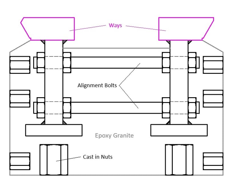
The Hi Lo Metal Lathe design has flat bar Ways that are stitch-welded to vertical webs, which in turn are also stich-welded to the bottom flat bars. The welding will cause some distortion, however, the I-beam design with opposing stitch-welds should help to keep the distortion to within acceptable limits. Each I-beam Way is welded separately.
One major design feature is that the two Ways are then bolted together with the ‘Alignment Bolts’. The bolts can be adjusted such that the top of the ways can be made co-planar, and the inside edges of the Ways can be made parallel. The ‘alignment bolts’ of the two Ways can be adjusted for as long as necessary to achieve a close alignment.
The whole assembly is then placed in a box mould and filled with an epoxy granite mixture. The resultant Bed and Ways will become a solid monolithic mass and will have good vibration dampening characteristics. Epoxy granite has been proven to be superior to steel or cast iron in this respect
The base will also have various rows of nuts set into the epoxy granite to allow for the attachment of ancillary parts, i.e., rack, feed screw, and future feed screw drive, and perhaps DRO fittings.
Once the epoxy base has cured, the top surfaces and inside edges of the Ways can be refined by grinding, sanding and scraping. Initially, the Saddle plate will slide on the top surfaces and inside edges of the Ways and these are the surfaces that need to be fairly accurate.
Later, the Saddle plate will first become a ‘Saddle Jig’ that holds the angle grinder, and this arrangement will be used to cut the 60-degree dovetails on both the Ways and the other dovetails in the project, and any other sections that would benefit from clean cutting.
The Ways can either be standard 20x50mm flat bars or a recent idea from the wooden mock-up is to have the Ways laser cut in one piece as shown below.


We will send you a free copy of these Lathe Design Notes (PDF file)
by entering your Name and Email below ...or you can visit the My Store pages and download from there ...
Hi Lo Metal Lathe
Build your own metal lathe
Enquiries
info@hilometallathe.com
© 2024. All rights reserved.
