Design Overview
The goal is to build a metal lathe that has good performance and a relatively low cost, and to build it without the aid of outside machine shop services where possible.
The size of the lathe will be modest and able to be setup on a workbench. The design target is for a 260mm (~10”) swing, a length between centres of around 720mm (~28”), a Spindle bore of 25mm (1”) and a Tailstock Spindle movement of 130mm (~5.5”).
In this design, I use simple methods while allowing a degree of precision to be built into the machine. The best advice for a DIY lathe project is ‘If you can’t make it accurate, make it adjustable.’ With good design, suitable for the home builder, we can make it such that the critical alignments are adjustable.
The main items that set the whole project going are the purchase of a 150mm 4-jaw chuck and the hollow bar pieces for the Headstock and Tailstock Spindles.

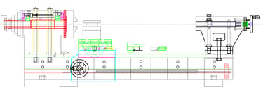
The Ways, Headstock and Tailstock components will be cast into an epoxy granite mixture, as shown. This method will allow better alignment of the Ways, the Spindle bearing housings and Tailstock components.
The use of epoxy granite is well proven and will also add mass and provide superior vibration dampening. Using epoxy is simply a matter of mixing parts A + B and this project will make good use of the advantages and capabilities of epoxy.
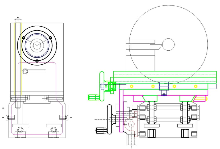

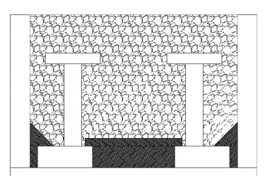

The two Ways will be simple 60-degree dovetailed sections.
This format has been proven with many factory-built lathes and is more easily achievable by DIY enthusiasts compared to the two ‘Flats’ and two ‘Vees’ currently in production.
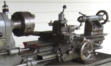

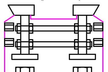

The cost of having the Saddle and Tailstock on the same Ways is that the Tailstock cannot come as close to the Headstock due to the space taken by the Saddle on the same Ways. I’ll live with that, as the work to reproduce the flats and vees, and then translate those into the Saddle and install the appropriate Gibs, is significant and not really feasible without the use of a substantial milling machine. Having stated that as an issue, the length of a drill chuck, plus the length of the drill bit, may be such that this is generally a non-issue.
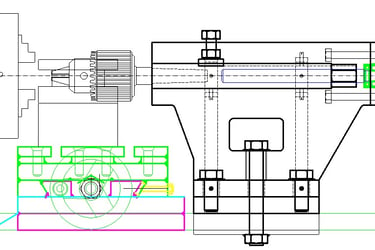

The design will make full use of laser cutting services. Many of the parts will be laser-cut, some from 20mm plate and others from 12mm plate. These two thicknesses were found to cover most requirements and also save a great deal of cutting and grinding with the angle grinder, not to mention a superior finish. A good example is having the rings that will house the Spindle bearings and oil seals laser cut.


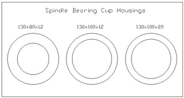

We could purchase steel in standard bar and plate sections and be prepared to do a lot of cutting and grinding using the angle grinder. Tough, time-consuming and noisy work. The design is such that we can avoid a lot of that work by having the majority of the components laser cut to exact dimensions.
Too much cutting, grinding and filing is not so enjoyable. Let’s spend our time with the more satisfying tasks like alignment and finishing. Note the YouTube comment below …


The Hi Lo design has tapered roller bearings for the Spindle. Many DIY, and even factory-purchased lathes, have simple ball bearings that are not fit for purpose as Spindle bearings. Play cannot be removed from ball bearings, and vibration is guaranteed. Furthermore, all DIY lathes that I have seen do not protect their tapered bearings with oil seals and also rely on regular greasing. The greasing and open bearings are a magnet for swarf to enter and quickly destroy the bearings. Oil seal housings are easily made by laser-cut rings, and the tapered roller bearings can run in a bath of oil behind the oil seals.
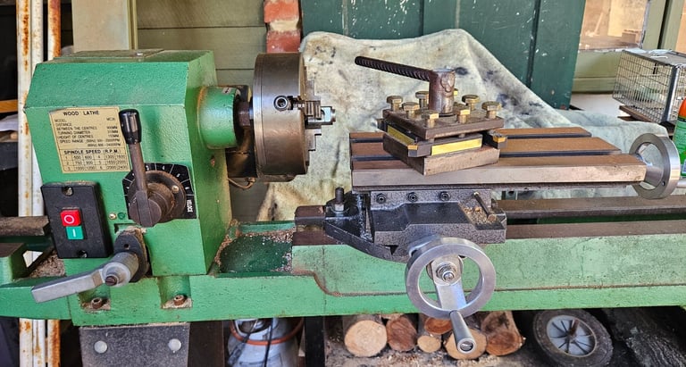
I have also experimented with 'scraping' to achieve a high degree of flatness and found it to be a very approachable method. The picture below is of a scraped plate that slides along the ways of the wood lathe setup. A satisfying job in itself …
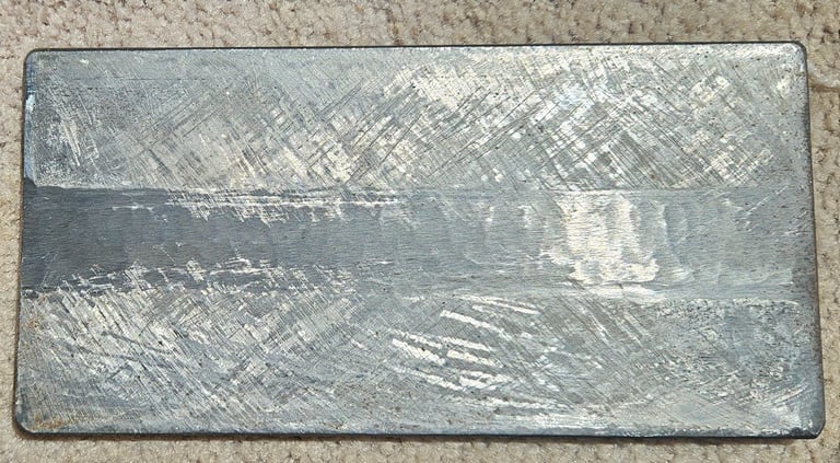

The great thing about hand scraping is that the degree of tolerance is up to you, and you can always re-scrape sections to improve on precision at a later date. A decent scraper can be made from a file, and a ‘good enough for now’ surface plate can be made from a piece of thick glass, a piece of stone benchtop, or any other suitably sized ‘flat’ object.
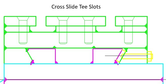

The cross slide will have two ‘Tee’ slots on its top surface to allow different types of setups to be used, e.g., bolting on the compound slide or milling attachments, different tool holders, etc
The ‘Wood Lathe setup’, as described on the Home page and shown below, will be used to machine the Spindle. If you don’t have such a setup, then this is the one item that may have to be machined at a machine shop. A detailed Spindle drawing will be available on this site.
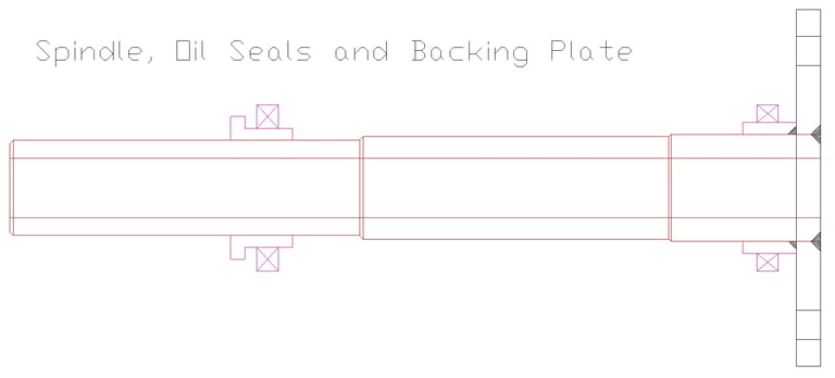


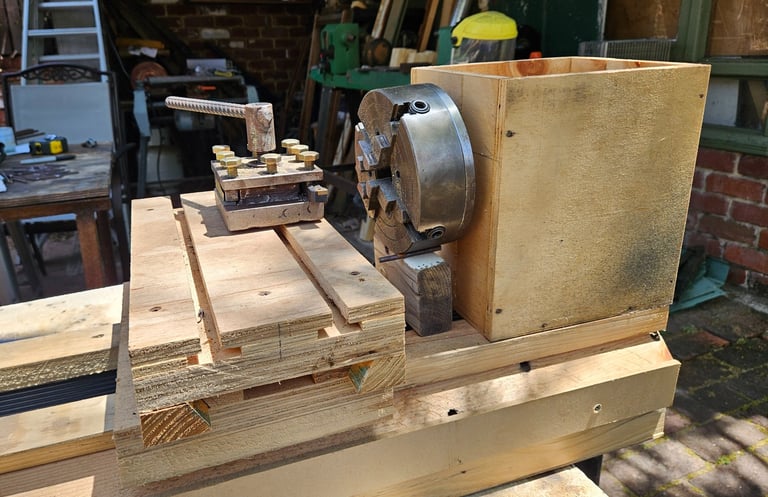
The design will be initially built as a wooden model. I have made the first mock-up of the lathe Bed and Ways, and also the Headstock. The model has already revealed areas that can be further improved.

We will send you a free copy of these Lathe Design Notes (PDF file)
by entering your Name and Email below ...or you can visit the My Store pages and download from there ...
Hi Lo Metal Lathe
Build your own metal lathe
Enquiries
info@hilometallathe.com
© 2024. All rights reserved.
