Rack and Pinion
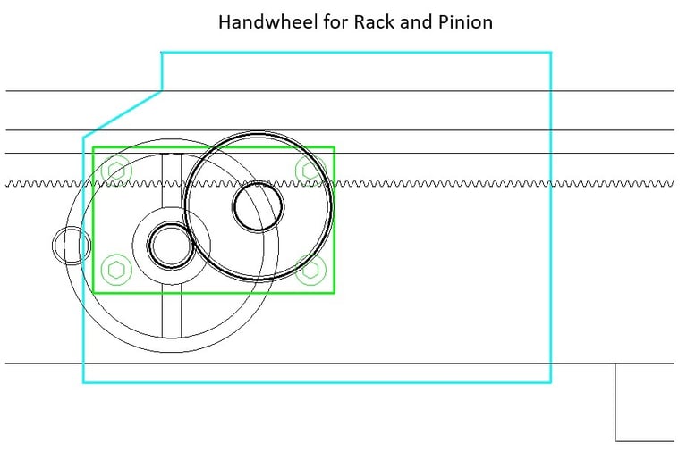
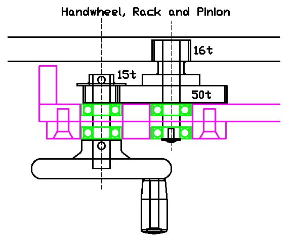
The Rack and Pinion system enables the Saddle to be moved manually, by way of the handwheel, along the Ways. As soon as the Cross Slide has been made, the lathe turns into a functioning machine. The power Feed Screw system will be added later.


We will send you a free copy of these Lathe Design Notes (PDF file)
by entering your Name and Email below ...or you can visit the My Store pages and download from there ...
Some DIY designs have used a length of chain and a sprocket as the manual drive mechanism, rather than a rack and pinion. Although perhaps a cheaper system, it could well take more work than the rack and pinion, and to be truly usable, the sprocket movement would need gearing down. I imagine that the result would be somewhat rough and complicated, and not do justice to this project.
For the cost of a length of rack, and three gears, we can have a nicely geared manual feed for the Saddle.
The gear shafts run in ball bearings to give a smooth and professional feel. Holes are laser-cut into the Apron to accept the bearings. The holes are cut slightly larger than the bearing O.D. and the bearings are epoxied in. This arrangement allows for some bearing movement to allow precise gear alignment and meshing.


Hi Lo Metal Lathe
Build your own metal lathe
Enquiries
info@hilometallathe.com
© 2024. All rights reserved.
