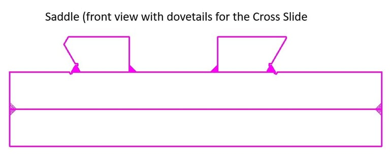
Saddle
The Saddle slides longitudinally along the Ways and provides the base that supports the Cross Slide and is made from laser-cut 20mm plate.
Initially, the Saddle plate will register between and under the inside edges of the Ways, as shown below. The sliding top plate will be used to mount the angle grinder, and this ‘Saddle Jig’ will be used to cut the dovetails of the Ways and Cross Slide, and other cutting jobs in the project.


We will send you a free copy of these Lathe Design Notes (PDF file)
by entering your Name and Email below ...or you can visit the My Store pages and download from there ...
After the dovetails have been cut, the Saddle dovetail sections will be stitch-welded to the Saddle plate, as shown below in the side and front views. Opposing stitch-welds on either side of the plate will be done to counteract and minimise distortion.
An adjustable ‘gib strip’ bears against the dovetail surface of the rear Way to ensure that the Saddle is held in close tolerance to the Ways in both the side-to-side and up and down directions.
Following the welding, bluing and grinding/scraping work will be done to refine the mating surfaces between the Saddle and the Ways. The bluing and scraping work can be continued until satisfied of the precision of the contact surfaces.


Later in the project, it would be entirely feasible, and not expensive, to fit an X-axis DRO (Digital Read Out) to display the precise Saddle position.


Hi Lo Metal Lathe
Build your own metal lathe
Enquiries
info@hilometallathe.com
© 2024. All rights reserved.
